Effective silicone compression molding begins prior to production – it begins with a part design that resonates with silicone material behavior, mold flow, demolding needs and production control that is reproducible.
A lot of molding issues that occur in production are not due to machine settings or the errors of the operators. They are based on designs that disregard the flow, curing, shrinkage and release of silicone out of the mold. One of the most widespread myths is that when you have a good 3D model, any other factory is able to shape it without any problems. As a matter of fact, silicone compression molding requires premature design-for-manufacturability (DFM) considerations.
An effective silicone compression molded component is not just an effective product design; it is a production design which balances functionality, material performance, mold structure, tolerance control, and quality check.
Start With Product Function Before Part Geometry
The whole design process of silicone compression molding should be product-function based rather than vice versa.
Draw geometry before worrying about aesthetics: now clearly specify how the part will work in practice. Will it withstand the pressure? Provide grip? Withstand repeated compression? Heat or chemical-resistant? These utility needs directly ascertain durometer, wall thickness, flexibility, and surface needs.
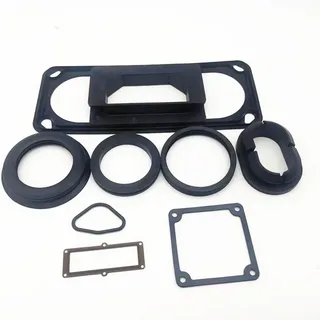
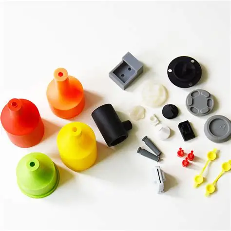
To illustrate, an automotive silicone gasket would be more concerned with compression set and dimensional stability. The handle of a kitchen utensil must be grippy and safe to use with food. A pet toy should be tear resistant and soft. Every application has its design logic, although they all utilize the same family of base materials.
In projects with constant dimensions and where repeatability of fit is needed then early design review must consider the product functionality with high precision silicone molding and not using it as a correction tool once the design has been finalized.
Keep Wall Thickness as Consistent as Possible
The most significant aspect of silicone compression molding design, which is often neglected, is consistent wall thickness.
Drastic changes in thickness provide uneven flow of material, uneven curing, and internal stresses which result in warping, sinks or uneven mechanical properties. Silicone will cure outside to inside; therefore, thicker components take longer to cure whereas thin silicone can over-cure or tear.
Recommended wall thickness guidelines:
| Wall Thickness Design Issue | Possible Production Risk | Better Design Approach |
| Sudden thick-to-thin transition | Uneven curing or filling | Use gradual transitions |
| Overly thick sections | Longer curing time, deformation | Reduce mass or adjust geometry |
| Very thin edges | Tearing or incomplete filling | Increase edge support |
| Inconsistent wall areas | Dimensional variation | Balance thickness where possible |
| Thick decorative features | Extra flash or air trapping | Simplify or reposition features |
Where variable thickness must be used due to reasons of functionality, ensure transitions are as gentle as possible, preferably with large radii, and discuss with your molding partner in advance.
Plan Draft Angles and Demolding Early
The initial concept stage should consider draft angles and demolding characteristics, rather than the first sample tearing or sticking.
Silicone is very flexible, but bad draft may also lead to the stretching, distortion, or tearing of parts during ejection. Problematic features are deep straight walls, sharp internal corners, and unsupported thin features.
Key demolding considerations:
| Design Feature | Demolding Risk | Recommended Consideration |
| Deep vertical wall | Sticking or stretching | Add suitable draft angle |
| Sharp internal corner | Tearing stress | Use radius design |
| Thin protrusion | Damage during release | Increase support or adjust position |
| Undercut | Difficult mold release | Review mold split or redesign |
| Soft material area | Shape deformation | Improve demolding direction |
When finalizing geometry, always consider direction of mold opening and ejection pins or air assist.
Use Radii Instead of Sharp Corners
Sharp corners cause stress concentrations which influence both the performance of the molding as well as the long-term performance of part.
Silicone compression molding material is not able to easily flow into the sharp parts and these are the weak points when demolding and usage is required. Radii enhance flow, minimize trapped air, and evenly distribute stress.
- Apply radius to inside corners where tearing can be.
- Do not use knife-edge features unless essential.
- Apply rounded edges between thick and thin.
- Look at minor details of decoration, which are not necessarily shaped.
- Balanced appearance and mold release and durability.
A minimum radius of 0.5 mm can usually be feasible, but functional considerations can dictate larger values.
Design Parting Lines and Flash Areas Intentionally
Parting lines Parting lines are unavoidable in compression molding, and determine the location of the flash.
Intelligent designers design around the location of the parting line rather than struggling with it in future.
The best practices in parting line placement:
| Area of the Part | Parting Line Concern | Design Recommendation |
| Sealing surface | Flash may affect function | Avoid parting line if possible |
| Visible surface | Aesthetic defect risk | Move line to less visible area |
| Assembly fit area | Dimensional interference | Keep tolerance zones clear |
| Thin edge | Flash trimming difficulty | Add support or adjust edge design |
| Textured surface | Inconsistent finish | Review mold split carefully |
Embrace that there will be flash and create features in designs that allow easier and more consistent trimming.
Consider Material Flow and Preform Placement
Compression molding In compression molding, the positioning of the preform (raw silicone charge) has a big influence on how the material will fill the cavity.
Flow-related design considerations:
| Design Condition | Flow-Related Risk | Better Design Direction |
| Long narrow channel | Incomplete filling | Increase flow path or adjust geometry |
| Isolated small feature | Air trap or short fill | Add venting or modify feature |
| Large flat area | Uneven pressure distribution | Review preform placement |
| Multi-cavity layout | Inconsistent filling | Balance cavity design |
| Complex decorative detail | Poor definition | Simplify or adjust feature depth |
In sampling, experienced engineers tend to change the preform shape and weight to achieve optimal fill without too much flash.
Define Realistic Tolerances for Silicone Parts
Silicone does not act like hard plastics or metals. It is more forgiving to tolerances due to its elasticity and shrinkage (usually 1.53% by grade).
Practical tolerance planning:
| Tolerance Planning Item | Why It Matters | Recommendation |
| Critical fit dimensions | Affects assembly and function | Define clearly on drawing |
| Non-critical dimensions | May not need tight control | Avoid unnecessary tight tolerances |
| Material hardness | Influences measurement stability | Match tolerance to Shore hardness |
| Shrinkage allowance | Affects final size | Confirm during sampling |
| Inspection method | Impacts measured result | Align measurement standard early |
Unrealistic tolerances increase tooling cost and scrap rates yet have no effect on real-world performance.
Choose Silicone Hardness Based on Function
The choice of durometer is a very important design choice and influences almost all the performance and manufacturability of parts.
Hardness considerations:
| Silicone Hardness Consideration | Design Impact |
| Softer silicone | Better flexibility, higher deformation risk |
| Medium hardness | Balanced handling and function |
| Harder silicone | Better structural support, less flexibility |
| Sealing requirement | Requires compression and recovery balance |
| Grip or touch feel | Requires user-experience testing |

Never trust the datasheet values to determine hardness choice but always test it with functional prototypes.
Avoid Overcomplicated Details That Do Not Add Function
Intricate specifications that appear dazzling in the CAD usually cause headache in the production process.
- Do not use excessively thin ribs which tend to tear or stuff badly.
- Make molded logos plain and understandable.
- Minimise deep grooves in malleable regions.
- Establish the influence of texture on demolding.
- Select secondary finishing where detail in the form of a mold is not feasible.
With simplicity, there is a tendency to produce quality and cheaper.
Design for Secondary Processes and Assembly
The majority of silicone components have post-molding operations. Start planning them out early in advance.
Secondary process requirements:
| Secondary Process | Design Requirement | Risk If Ignored |
| Trimming | Accessible flash area | Uneven edges |
| Silk screen printing | Flat or stable surface | Poor print consistency |
| Spray coating | Clean exposure area | Uneven finish |
| Laser engraving | Suitable surface and contrast | Weak readability |
| Assembly | Proper flexibility and clearance | Tearing or poor fit |
Prototype and Sample Before Production Tooling
Always take adequate sampling. A design which appears ideal in CAD may have some unforeseen problems when molded in real silicone.
Essential sample review checklist:
| Sample Review Item | What to Check |
| Fit and assembly | Does the part fit the intended product? |
| Flexibility | Does the hardness meet use requirements? |
| Surface quality | Are there marks, bubbles, or flash concerns? |
| Dimensional stability | Are critical dimensions controlled? |
| Demolding result | Are there signs of tearing or deformation? |
| Functional performance | Does the part seal, protect, grip, or support as intended? |
Design iteration: Use sample feedback to repeat the design before cutting production tooling.
Typical Designs Fallacies in Silicone Compression Molding.
Common Design Mistakes in Silicone Compression Molding
Even the seasoned teams occasionally fall into the following traps:
- Designing without considering manufacturability.
- Inconsistent thickness of the walls.
- Demolding and draft angles ignored.
- Using metal tolerances that are applied to plastic parts.
- Application of parting lines on important sealing or exposed surfaces.
- Including superfluous acute angles or small ornamental features.
- Selection of silicone hardness with no functional testing.
- Not having thought about a trim, print or assembly.
Conclusion — Better Design Leads to Better Molding Results
The combination of design and manufacturing leads to successful silicone compression molding. By considering material behavior, mold release, flow, tolerance control and secondary processing when designing a silicone part, stable, functional and repeatable custom silicone parts become easier to produce.
Using these silicone compression molding design tips, consisting of uniform wall thickness and correct draft angles, realistic tolerances and considerate parting line location, engineers and OEM teams can greatly minimize defects, tooling rework, production time and cost.
Early cooperation between product designers and knowledgeable silicone manufacturers familiar with the material and the process give the best results. Considering silicone part design in the front always will make a payoff in the back in quality and efficiency.