Silicone check valves are single piece, passive, flow-control components that work as a single valve and open by flow when the fluid is pushing forward, and remain tightly closed when the fluid pressure is reduced. The check valve can be in the shape of a duckbill, umbrella, or cross-slit. Silicone membrane valves (also known as diaphragms) are flexible membranes which, when pressed against a mating seat, form a sealing barrier and can be mechanically, solenoid or pneumatically activated to isolate multiple channels or for precise regulation.
In OEM fluid system projects such as automotive fluid systems, medical or small appliances, their selection will directly affect both silicone valve performance and reliability, and long-term cost. Check valves are ideal for simple, line-veiled backflow prevention, and membrane valves are best suited for sealing over wide areas or for high cycle applications. Choosing the right profile at the outset of design helps to avoid leaks, minimise assembly processes and plan tooling budgets.
It’s easy to see how many sourcing managers and junior engineers would think that a flexible membrane can be used to eliminate an inline check valve and save space. This perception is frequently an obstacle to problems. A membrane works very well to provide dynamic surface sealing over wide area but does not have a self collapsing geometry like the duckbill or cross slit valve. If one is substituted in place of the other without redesigning the fluid path then the fluid path is likely to leak at low pressure and the flow coefficient will not remain consistent.
Mechanical Architectures and Fluidic Behaviors
The actual difference is revealed by the response of each valve to pressure and flow. A silicone check valve uses the inherent geometry and hoop stress properties. If there is forward pressure, the lips or slits move open cleanly; when the pressure is reversed, the lips or slits close with increasing seal power. This is passive and allows them to be used to protect against one-way flow in fuel lines, pump outlets or drainage systems.
Silicone membrane valves, however, are deflectable walls. They are flat until acted on by an external stimulus, such as actuation, or differential pressure, exceeding their resting tension. This design allows for multi-port control and very low cracking pressures over a large area.
When designing micro-fluidic arrays or automotive pump assemblies, mapping out the precise deflection boundaries of your silicone valves and elastomeric flow control components prevents localized structural stress and ensures long-term fatigue resistance.
| Engineering Metric | Silicone Check Valves (Duckbill/Umbrella) | Silicone Membrane Valves (Diaphragms) |
| Primary Fluid Function | Inline backflow prevention & localized pressure relief | Multi-channel flow isolation & active pressure regulation |
| Actuation Mechanism | Passive (Driven strictly by media head pressure) | Active or Passive (Solenoid, pneumatic plunger, or surface pressure) |
| Cracking Pressure Range | Highly localized (Can be engineered from low to high thresholds via slit layout) | Broad surface distribution (Responsive to ultra-low pressure deltas) |
| Particulate Tolerance | High (Elastomeric lips flex and compress around pulp/debris) | Moderate to Low (Particulates trapped on the mating seat induce leakage) |
| Tooling Complexity | High (Requires precision core pin concentricity and slitting jigs) | Moderate (Requires exceptional flatness and gate flash control) |
Behind the Scenes: The Manufacturing Reality and Tooling Challenges
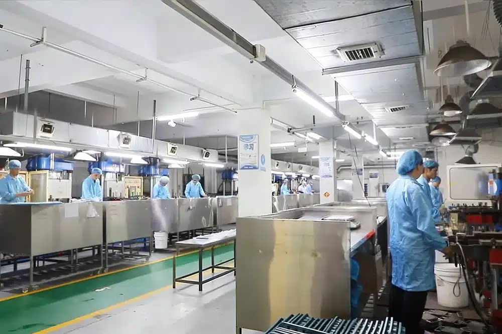
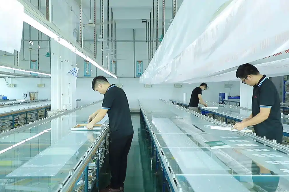
In our Dongguan factory, the real production distinction is actually witnessed on a daily basis. In the case of check valves, concentricity of the cores is all-important. The 0.03mm shift in molding process results in unequal wall thickness. One side develops weakness and early buckling or cracking pressure is not uniform. This is the reason we use precision core pins and precision custom automated slitting fixtures; manual slitting results in a ragged edge and raises fluid trailing and contamination risks.
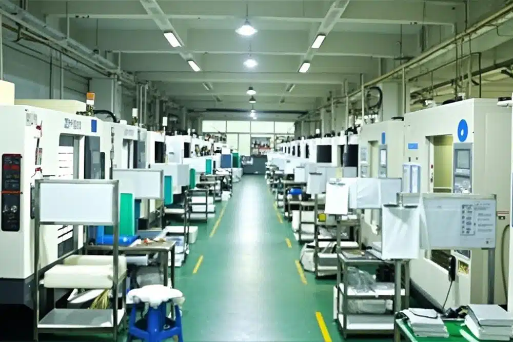
Membrane and diaphragm valves are met with other challenges. They are prone to warping from unequal cooling because of their wide, narrow shape. During vulcanization, there are internal stresses which can result in the part curling after ejection, which in turn can prevent forging a flush seal with the customer’s housing. Guaranteeing production of these consistently requires high quality liquid silicone rubber (LSR) and requires precision-machined injection systems with well-balanced cooling channels and a flashless mold design. These are key factors that are under our control thanks to our in-house mould manufacturing workshop.
Shop-Floor Failure Modes and Corrective Countermeasures
Patterns that are not reported in the datasheet are discovered during real production validation runs. Typical peroxide cured silicone has a tendency to lose the “snap” after thousands of cycles in high-pulsation environments, which causes compression set. Typically, conversion to a high-tear platinum-cure LSR will bring back elastic memory and dramatically increase service life.
| Field Failure Mode | Root Cause in Part Design / Tooling | Factory Countermeasure & Control |
| Low-Pressure Weeping | Asymmetric wall thickness from mold core shift or flash on the split-line | Utilize rigid centering interlocks in the tool steel; employ flashless overflow mold layouts |
| Diaphragm Wrinkling/Curling | Internal molding stresses caused by uneven cooling paths or improper gate setup | Optimize cooling line balance across the cavity plate; position injection gates far from flex zones |
| Premature Material Tearing | High mechanical shear stress on sharp, non-radiused internal corner steps | Enforce a minimum corner radius of 0.3 mm to 0.5 mm during the initial DFM drawing audit |
| Aperture Fusion / Sticking | Volatile cyclosiloxanes remaining on the slit edges after mechanical slitting | Conduct extended secondary forced-air post-cure bakes at 200°C; apply anti-bonding surface sprays |
Sourcing Checklist: Questions to Ask Before Tooling Kick-Off
Ahead of releasing files for quotation, have a meeting with your team and potential manufacturing partner to discuss the following:
- Chemical Aggressiveness of medium: Does the medium contain chemicals that are aggressive? Automotive applications might require fluorosilicone blends, and infant feeding applications might require platinum-cure.
- Viscosity vs. Aperture: If the check valve slit length has not been calculated correctly for thicker syrups or pastes, they may cause shearing blockages.
- For membrane valves, is there sufficient clearance in the housing for the highest point of deflection of the diaphragm?
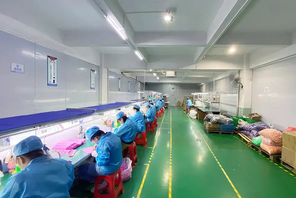
- Environment Cleanliness: Does the final assembly need zero particle contamination? Verify that the supplier has a workshop and assembly area that is certified as dust free.
- Modeling of Wall Thickness Cracking Pressure: Have you modeled the behavior of custom silicone valve profiles under forward and backward pressures over the range of temperatures you are expecting?
- Long-Term Fatigue: What is the desired cycle life and has the material been tested to see if it performs with 0 leakage for that cycle life?
Conclusion — Seamless Integration Requires Complete System Control
The silicone check valve and membrane valve can provide excellent sealing performance when used appropriately and manufactured correctly. The key is not merely to select a compound from a catalog, but rather to ensure tight dimensional control, think through the design, and understand the fluidic environment for successful outcome.
The whole process—from the in-house manufacturing workshop of the mould to the precision slitting control, dust-free assembly and packaging workshop of the mould—with the manufacturer that controls it all, eliminates variables that lead to field failures. Delivering reliable, single-piece fluid control solutions that deliver consistent performance from prototype to high-volume production for our OEM teams, that is what we do at Dongguan HT Silicone & Rubber Co., Ltd.